Most machining issues have simple causes once you look closely. Parts rarely fail because of one major mistake. More often, it’s a collection of small changes—heat, tool wear, chip flow, clamping pressure, or the way the material reacts when metal is removed.
What follows is a practical walk-through of the defects that show up most often, why they happen, and what machinists typically do to keep them under control.
Why CNC defects occur
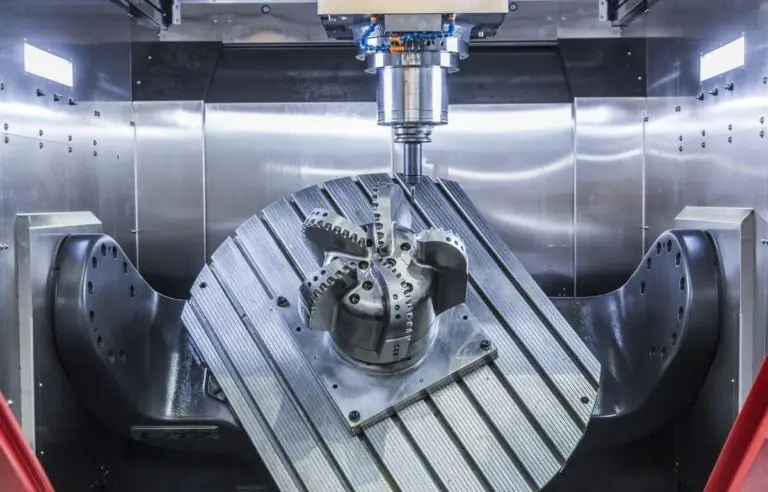
Machining isn’t just a tool cutting metal. It’s a mix of cutting forces, heat, vibration, material behavior, and how the part is held. A tiny shift in any of these can change the outcome.
A part might expand because it gets warm, or shrink slightly as it cools. A tool that was sharp in the morning may cut differently by the afternoon. Internal stress inside the material can suddenly release after a heavy cut. Even small decisions—like the order of toolpaths or how tight a clamp is—can affect the final shape.
Once you think of machining as a chain of connected steps rather than a single action, defects start to make more sense.
Dimensional errors
Size issues show up when something in the process drifts. Tools slowly lose their sharpness, removing less material than expected. Heat causes the part—or even the machine—to grow slightly. If clamping isn’t stable, the part may shift a fraction during cutting.
Some materials carry residual stress from how they were manufactured. Once the outer layer is removed, the part may move on its own.
Machinists usually deal with this by cutting in stages, letting the part relax, checking tools regularly, and keeping fixturing as steady as possible. Monitoring trends in size during production also helps catch drift early.
Surface finish defects
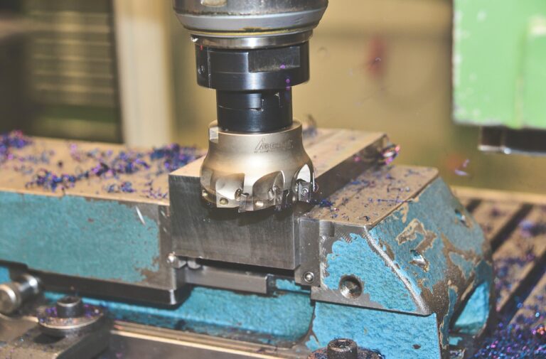
A rough or torn surface usually means the cutting edge isn’t doing its job cleanly. A dull tool tends to rub instead of slice. Too much vibration leaves small waves or ripples. Chips sticking to the edge can scratch the material.
Surface discoloration, burnt patches, or shiny “dragged” areas often point to heat buildup or coolant not reaching the cut.
Smoother parameters, sharper tools, a more rigid setup, and a proper finishing pass usually bring the surface back to what was intended.
Chatter and vibration patterns
Chatter has a very recognizable look—repeating marks or waves along the surface. It happens when the tool, holder, or part begins vibrating at the wrong moment. Long tool overhangs make this more likely. Some materials also encourage vibration if the speed isn’t right.
The fix is usually straightforward: reduce the tool length, tighten the setup, or change the cutting speed until the vibration settles down.
Burrs and edge problems
Burrs are a natural result of metal being pushed out at the end of a cut. Softer materials form them more easily, especially when tools start to dull.
If the tool exits the cut sharply, burrs tend to be larger. That’s why many toolpaths are planned to ease out gently rather than “snap” out.
Better tool condition, controlled chip flow, and a planned deburring step usually solve these issues.
Warping and deformation
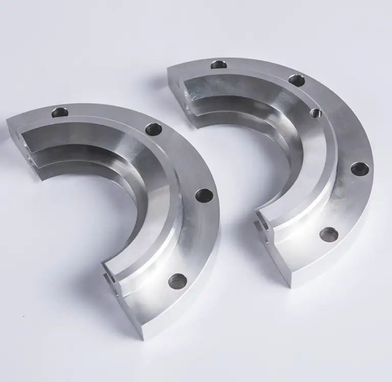
Some parts don’t stay flat after machining, even if the cutting looked perfect. This is almost always internal stress being released.
Long, thin parts or plates bend easily because removing material from one side changes how the metal balances its internal forces. Thin walls may flex away from the tool, then spring back once the tool leaves.
Machinists use balanced cuts, stress-relief steps, lighter finishing passes, and careful support to keep the part stable.
Heat-related defects
Too much heat during cutting can darken the surface, harden certain materials, or leave visible burn marks. Materials like titanium don’t carry heat well, so the tool ends up absorbing most of it.
High speed, heavy engagement, or weak coolant delivery all make this more likely.
Lowering cutting speed, improving coolant direction, and using more heat-resistant tooling help prevent these marks.
Chip-related defects
Chips can cause trouble if they stay near the cutting edge. When chips weld to the tool (built-up edge), the cutting action changes completely. If chips fall back into the cut and get re-cut, the tool and the surface both take damage.
Good chip evacuation, sharper tools, lubrication, and chip-friendly toolpaths keep this under control.
Marks related to toolpath choices
Toolpath marks—small steps, faint spirals, or overlapping lines—usually come from the chosen step-over or the finishing pattern.
Using the right cutter shape and selecting a finishing step-over that suits the geometry usually removes these traces.
Clamping and handling marks
Clamps are necessary to hold the part, but they can also leave dents or flats if the pressure is too high or the contact area is too small. Softer metals like aluminum show this quickly.
Soft jaws, protective pads, and wider support surfaces spread the force more gently.
Programming and process mistakes
Even experienced machinists can mis-set a zero point, choose the wrong tool number, or type a value incorrectly.
A missing simulation or an unchecked rapid move can create unexpected marks or even scrap the part.
Shops rely on dry-runs, simulations, and program sheets to keep this under control.
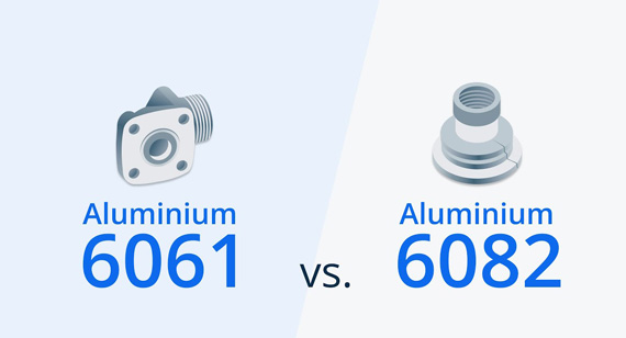
Material-specific issues
Every material behaves differently.
Aluminum burrs easily and grows with heat.
Stainless steel hardens as you cut it.
Titanium traps heat.
Plastics can melt, warp, or crack if overheated or clamped too tightly.
Knowing how each material reacts helps choose parameters and tooling that avoid predictable issues.
Methods used to reduce and prevent defects
Modern machining relies heavily on watching for patterns. Real-time monitoring—tracking tool load, vibration, temperature, and size trends—helps detect problems before they become visible. Statistical process control (SPC) turns gradual drift into something predictable.
Shops also reduce defects by using shared cutting-data libraries so everyone follows proven speeds and feeds instead of guessing. CAM templates make roughing and finishing more consistent from part to part.
For very precise work, closed-loop machining compares measurements taken during or after cutting and adjusts the toolpath automatically. This helps compensate for tool wear, heat changes, and deflection.
Building a stable machining process
A stable process starts long before cutting begins. Heat management, fixturing strategy, tool selection, wall thickness, and the order of operations all influence how the part will behave.
When these pieces are planned together, machining becomes much more predictable and defects become far less common.