In CNC machining, tolerances define how much a part’s actual size can deviate from its design value while still functioning as intended. Getting them right ensures proper fits, reliable performance, and cost-effective production.
What Are CNC Machining Tolerances?
Tolerance is the acceptable deviation from a nominal dimension. For example, a shaft designed at 2.550” with ±0.001” can measure anywhere between 2.549” and 2.551”.
- Tighter tolerances → higher accuracy, higher cost.
- Looser tolerances → easier and cheaper, but less precise.
Common Standard Tolerances
- General tolerance: ±0.005” (±0.127 mm), typical for non-critical features.
- High precision: ±0.002” (±0.051 mm) for tight fits.
- Reamed holes: As tight as ±0.0005” (±0.0127 mm).
- ISO 2768: International standard; fine class (f) is ±0.05 mm for 0.5–3 mm features.
Types of Tolerances
- Bilateral: Equal plus/minus, e.g., ±0.06 mm.
- Unilateral: Allowed in one direction only, e.g., +0.00 / -0.06 mm.
- Limit: Expressed as a range, e.g., 13.0–13.5 mm.
- GD&T (Geometric Dimensioning & Tolerancing): Adds control over form, position, and orientation beyond size.
Factors That Affect Tolerances
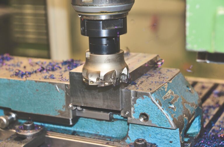
- Machine stability: Rigidity and thermal control determine accuracy.
- Tool condition: Wear, geometry, and cutting parameters matter.
- Material behavior:
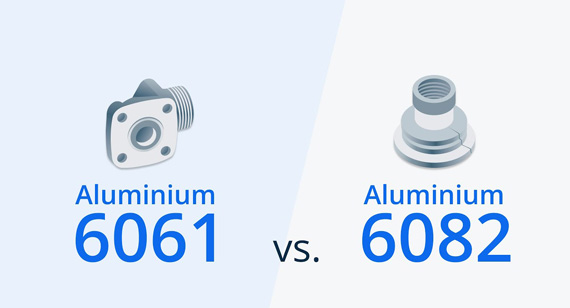
- Metals like aluminum and steel hold tighter tolerances.
- Plastics are more flexible and thermally sensitive, so tolerances must be looser.
- Hardness and abrasiveness: These drive tool wear and limit achievable accuracy.
Manufacturing and Cost Considerations
- Tight tolerances increase machining time, tool changes, and inspection needs.
- Costs rise quickly if tolerances are stricter than necessary.
- Reserve close tolerances for features like mating surfaces or sealing areas.
- Match tolerance demands with your CNC shop’s capabilities.
Typical Tolerances by Process
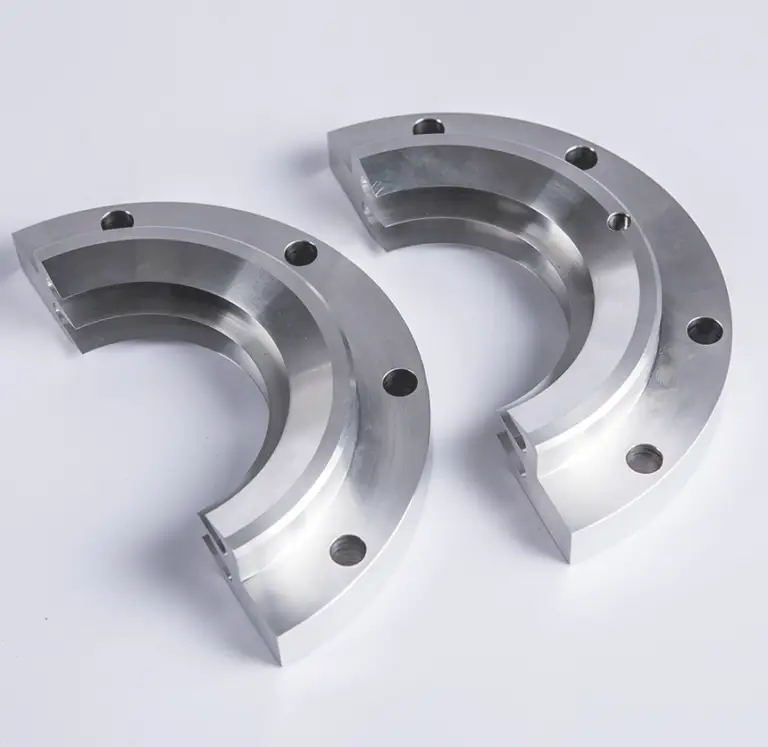
- CNC milling and turning: ±0.005” (0.13 mm) is common.
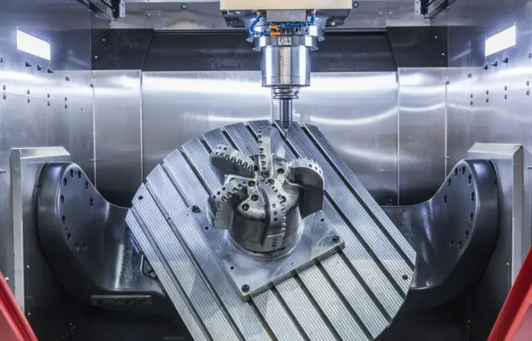
- 3-axis and 5-axis milling: ±0.005” (0.13 mm).
- Engraving and screw machining: ±0.005” (0.13 mm).
- Surface finish: Around 125 RA unless otherwise specified.
Practical Design Guidelines
- Tighten tolerances only where function requires it.
- Avoid over-specification, which leads to scrap and long lead times.
- Discuss tolerance requirements with your CNC supplier early.
- Always consider both material and machine limitations when setting tolerances.
Common Issues and How to Handle Them
| Issue | Impact | How to Address It |
|---|---|---|
| Overly tight tolerances on non-critical features | Higher cost, longer cycle times | Relax tolerances where performance isn’t affected |
| Using generic tolerances for all features | Risk of misfit in critical areas | Apply strict tolerances only to mating or sealing surfaces |
| Poor communication of requirements | Parts may not meet expectations | Provide clear drawings with GD&T symbols where needed |
| Ignoring material limitations | Deformation or scrap | Adjust tolerances based on material stiffness and thermal stability |
Tolerances are not about pushing every feature to the tightest possible value—they are about designing with intent. By understanding how tolerances affect cost, manufacturability, and performance, you can set requirements that keep parts functional while avoiding unnecessary complexity.